The ImageJ plugin SE_MTF (short for Slanted Edge Modulation Transfer Function) has been developed by Carles Mitja, Jaume Escofet, Aura Tacho and Raquel Revuelta at the Image Quality Laboratory (LQI, short for Laboratori de Qualitat de la Imatge) in the Center of the Image and the Multimedia Technology (CITM, short for Centre de la Imatge I la Tecnologia Multimedia) from the Polytechnic University of Catalonia (UPC, Spain).
The plugin performs system MTF calculations up to twice the Nyquist frequency over slanted vertical edge images with dark side at left; if the picture is taken from a horizontal slanted edge, the image must be rotated 90 degrees before running the plugin.
At the same time, the plugin run the calculations and shows as a result four plots labeled with the SPP_, ESF_, LSF_ and MTF_ prefixes respectively followed by the file name. ESF, LSF and MTF plots are calculated and traced as described in the MTF bibliography. SPP plot (short for Sampling Periodicity Plot) is a plot showing the result to apply the Fourier Transform Function to the series of the maximum values of the LSF used in the MTF calculations; the plot is a valuable indicator of periodicity sampling reliableness performed by the system because of the slanted position of the edge related with the sensor grid. In general, cheap cameras or scanners show a confused SPP with no clearly isolated peaks; conversely, a well calculated file from a professional camera or high end scanner shows a clearly isolated peak related with the number of pixel rows that is occupied by the period of sampling.
The four plots generated by the plugin takes the size and proportions from the previously selected options by the user in the Edit>Options>Profile plot options menu in ImageJ. The represented units are indicated in each plot and the user can take advantage of the three buttons below the plots in order to list, save or copy the plot values and export it as is usual in ImageJ. Finally, the plot images can be saved as TIFF for further use.
The edge can occupy the whole image (Fig., 1) or only a part of it, so the user can select a ROI to be analyzed (Fig., 2). The method used to calculate the MTF from a slanted edge is fully described in the bibliography (see references at the bottom of the page).
![Descripció: [Target_Whole]](IMG/1.bmp) Fig., 1
Fig., 1 ![Descripció: [Target_ROI]](IMG/2.bmp) Fig., 2
Fig., 2As usual in ImageJ, the file SE_MTF_2xNyquist.jar must be copied to the plugin folder or subfolder; after restart ImageJ, the SE_MTF label must appear in the Plugins menu. On play, it will open the SE_MTF frame with the button Generate MTF, as it is shown in the Fig., 3.
 Fig., 3
It is necessary to have an opened image prior to activate the Generate MTF button; otherwise ImageJ shows an Error frame with the message: There are no images open. Process cancelled; after pressing it, ImageJ can show one of the following messages:
o Warning, “All image selected” if there is no ROI selected in the active image window. The user can press the OK button and the plugin will use all image rows to calculate the MTF. If a ROI is selected, the message will not appear and the MTF is calculated from the pixels of selected rows.
o Error, "Line or rectangular selection required. Process canceled".
o MTF Options. This last frame takes different aspect related with the image bit depth and the units of the plots.
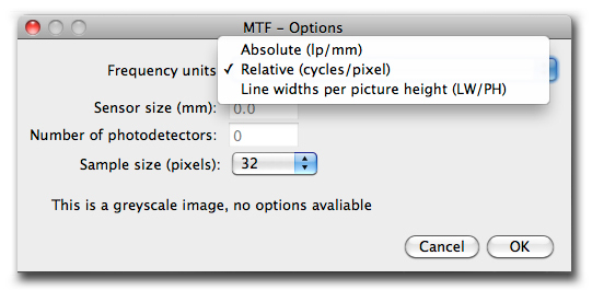
First of all, user can choose between three kind of units with whom the plots are going to be shown: Absolute (lp/mm), Relative (cycles/pixel) or Line With Per Picture Height (LW/PH).
 Fig., 4
Some of those options need additional information from the shot as the size of the sensor or of the number of photo detectors (the image could be a crop of a bigger one).
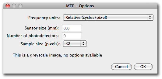
For images in greyscale mode, the MTF Options frame shows the message “This is a greyscale image, no options available” and the user can choose a sample size in pixels (32, 64, 128, 256 or 512); the figures are the number of pixels at the edge used to make the calculations and half the selected quantity is taken on both sides of the edge, Fig., 5. The different options can be used to take enough representative data both in images with low or high spatial resolutions. Obviously, the figure selected must be smaller than the image width or ROI selected; nevertheless, the plugin launch an Error message if the figure selected is bigger than the ROI or image width.

Fig., 5
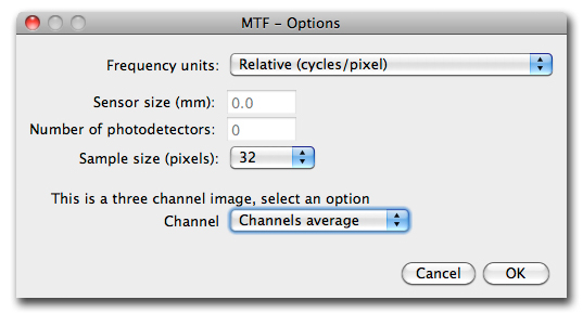
If there is an RGB image opened, the frame MTF Options offers to choose between select the R, G or B channel or to perform the average measure, Fig., 6; if the “Channels average” option is selected, the average is done as plain or weighted average depending on options selected in ImageJ Conversion Options (see ImageJ documentation). The R, G and B channels MTF can be calculated successively, selecting the appropriate option each time.
For images that ImageJ opens as an stack (16bit, etc.), the plugin offers the frame MTF Options as in the greyscale images and the calculations are done on the active slice; the user can make successive channel calculations or convert to an RGB image if channels average is preferred. Otherwise, if the needs are to calculate the channels average MTF the stack must be previously flattened with the Image>Stacks>Z Project>Average intensity command
 Fig., 6
 After the button OK is pressed, the user can find the messages:
o "Error”, “sample size is bigger than selection width. Process canceled". The sample size is the distance that will be analyzed from the edge sideways. If the sample size is bigger than the ROI, plugin cause an error.
o "Error", "Out of image bounds. Process canceled". If the edge is not centered on the image or is too tilted, sample size could not be the appropriate.
Bibliography
AXFORD, N. R. (1999) MODULATION TRANSFER FUNCTION OF A DIGITAL CAMERA SYSTEM USING AN IMPLEMENTATION OF THE EDGE TECHNIQUE. [En linea]. Pagina web, URL http://www.wmin.ac.uk/itrg/is/msc/mtflab.pdf [consulta 26/11/02].
BOREMAN, Glenn D. (2001) MODULATION TRANSFER FUNCTION IN OPTICAL AND ELECTRO-OPTICAL SYSTEMS. SPIE Press. Bellingham, Washington.
ISO / TC42N 4230 (1997) ELECTRONIC STILL PICTURE IMAGING. SPATIAL FREQUENCY RESPONSE (SFR) MEASUREMENTS. International Organisation for Standardisation.
JACOBSON, R. E., RAY, S. F., ATTRIDGE, G. G. y AXFORD, N. R. (2000) THE MANUAL OF PHOTOGRAPHY. Focal Press. 9th Ed. London.
MITJA, Carles. y ESCOFET, Jaume. MEDIDA DE LA MTF EN CAMARAS FOTOGRAFICAS DIGITALES, 7th Reunion Nacional de Optica, Universidad de Cantabria 2003, Santander.
WILLIAMS, Don y BURNS, Peter D. (2001) DIAGNOSTICS FOR DIGITAL CAPTURE USING MTF. Eastman Kodak Company. Rochester. PICS2001, Montreal (227-232).